![]()
![]()
![]()
![]()
![]()
![]()

![]()
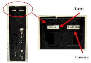
The SBC also has two Ethernet connectors, one for laser and the other for camera.
![]()
![]()
![]()
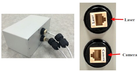
There are two waterproof Ethernet connectors at the back of the sensor, one for the stereo camera and the one for the laser scanner. Once you unscrew the connectors, you will find the labels indicating which connector is for the camera and which one is for the laser scanner.
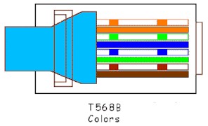
You need to crimp the RJ45 connectors to the Cat5 cable and follow the T568B standard of color order. Make sure to use an Ethernet tester to make sure that there are no mismatched wires in the Cat5 cable.
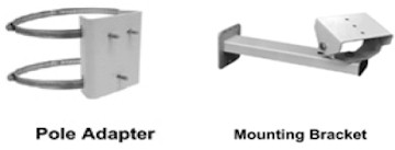
To mount the sensor to the signal pole, please follow the following steps:
(1) Attach the pole adapter to the signal pole
(2) Connect the mounting bracket to the pole adapter
(3) Mount the stereo camera on the bracket
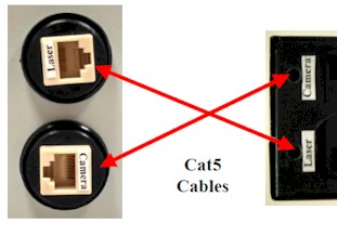
There will be two Cat5 cables, one for the laser and the other for the camera. Each Cat5 cable should connect to the corresponding connectors in the camera and laser scanner. For example, Cat5 cable for the camera should be plugged into the camera connector of SBC and camera connector of sensor. Similarly, the second Cat5 cable for the laser should be plugged into the laser connector of SBC and laser connector of sensor.